1. Cable construction
The wires were run through a thick-walled 4ft shrink tubing. The voltage drop on the heater supply was estimated to be about 0.5V based on the wire specification. This was later confirmed by measurements. Voltage drops in other lines are of no concern because the current is relatively low.


The finished product

2. Internals
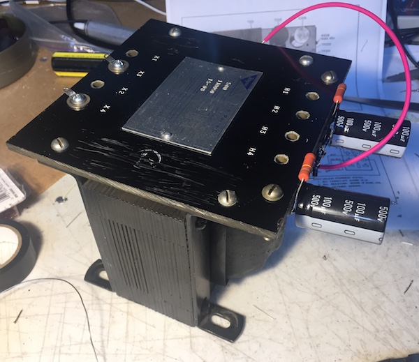
The original PS-500A-AC has a single power transformer supply all necessary voltages. Obtaining such a transformer is nearly impossible, so I opted to use multiple ones. The HV transformer is a used control transformer, which will produce 800V DC with not much voltage drop at the 500mA load. The transformer didn't buzz at all at 500mA current draw during the initial testing.
 |
 |
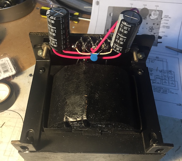
The bias is formed by a small 12VAC transformer connected backward to the heater supply. I was originally planning making a PCB for the supply, so bought a PCB mount version. The plan changed and I ended up wrapping it with a mounting cover that I saved from another project. A perfect fit! Then I've built the bias supply circuit on a small perf board.

B+ comes from a typical isolation transformer with the output at 230-240V AC. This will be rectified and fed to the voltage regulator for the 280V output. The schematic diagram for the PS-500A-AC says "280V at 100mA" for B+. This is clearly not the required current rating. If you add the maximum plate and screen currents for all tubes run on B+, it is close to 400mA. I originally used a 190mA transformer and it resulted in an overload and a huge voltage drop. I've doubled it and now it seems barely enough. I will update it to at least 500mA in the future.
Trying out a layout with the finished modules.

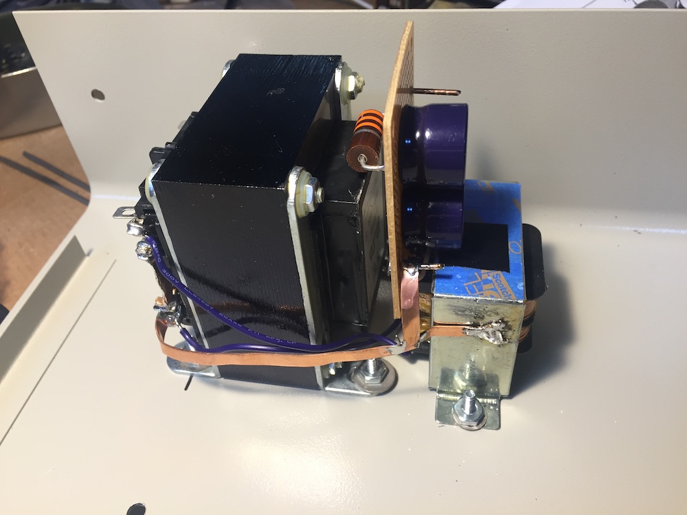
The heater and the bias supplies are mounted first as they go together. I added a thick ground bus as I was concerned about the chasis conductivity due to the excellent paint job. I did verify that all parts are well grounded.
After mounting all modules, I started on the back panel.

This was the initial layout. Since then, I have added a fan connector, which was added to the later version of PS-500A-AC. My SR-400 is a Cyclone II, but someone added a fan.

Wiring the back panel.

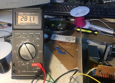
3. Output Voltages
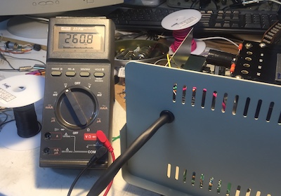
Once the back panel was wired, I was able to check the voltages at the wire end. The B+ was at 260V, so the regulator's reference voltage was adjusted. The regulator is a power MOSFET-based design. I bought it through the Old Radio Club in Korea. It was originally created for the Collins 516F-2 by HL5FTC and DS5TUK.
 |
 |
The heater was 14.87V unlloaded. At full load, it was measured to be 13.62V at the transformer and 13.02V at a tube base, only 0.6V more than the nominal 12.6V. The heater on 7059/7056 works on 12-15V. Others typically have more than +/- 1.0V tolerance.
Bias -125V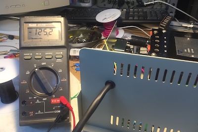 |
Heater 14.87V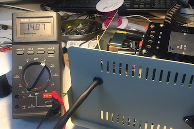 |
HV 820V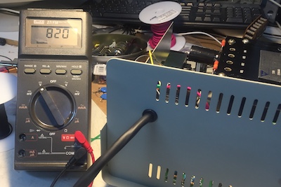 |
4. Adding a speaker
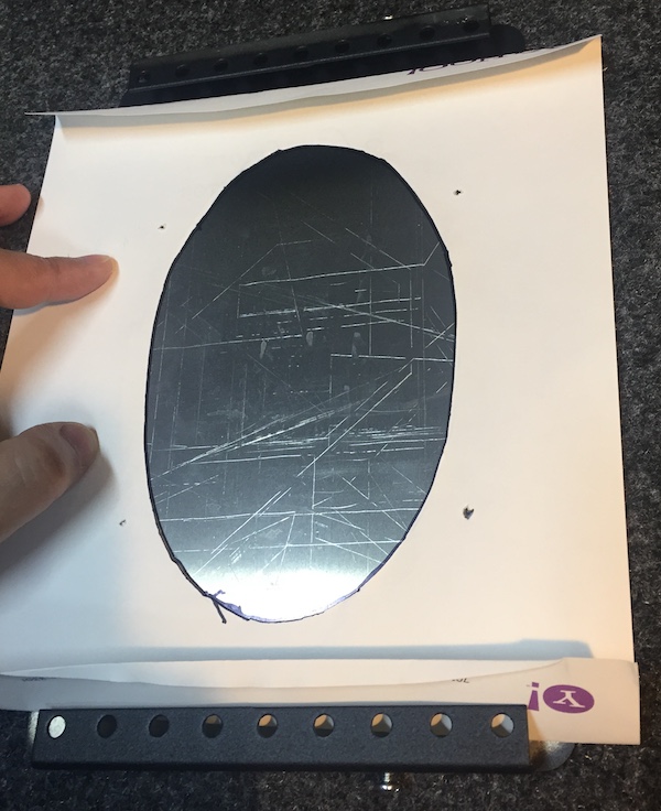
A speaker in a schematic diagram is not very exciting, but adding it to a DIY project is always a big deal. How do you make a hole? Where do you get a grille? It affects the look so much. I was thinking about transplanting an existing external speaker with its grille, but couldn't get one with the right size. So I ended up using an old speaker from a trashed Drake MS-4. I found a seller who custs and sells perforated steel plates. The description sounded reasonable and what I got was better than expected. It was cut perfectly to overlayed on the front panel.
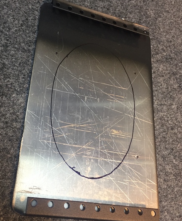
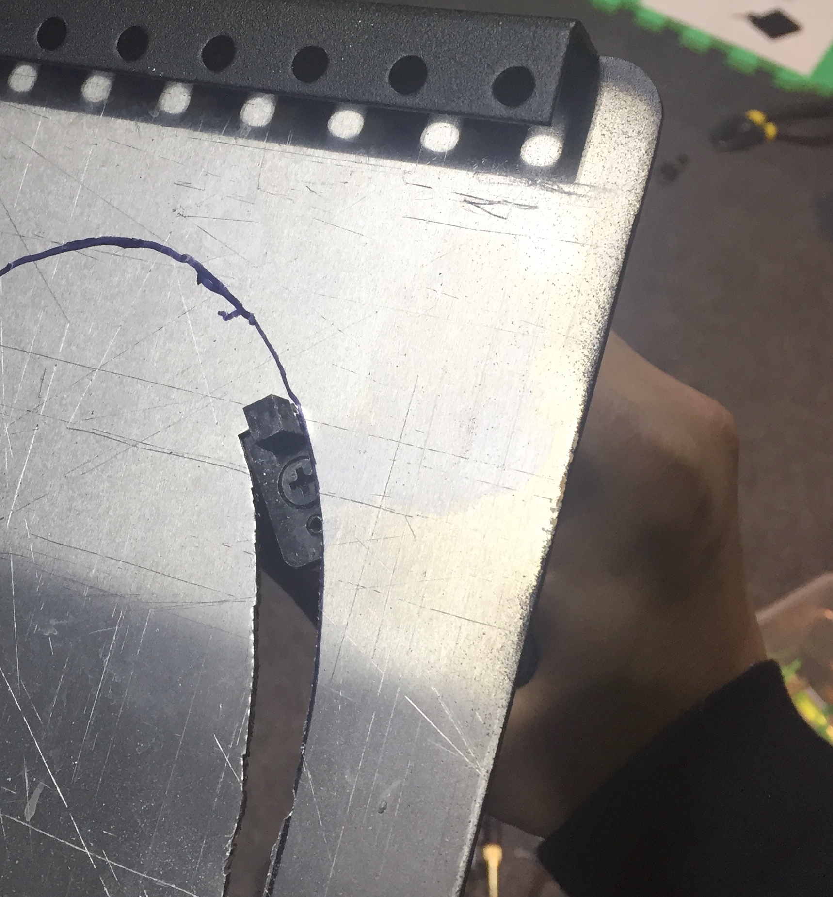
The biggest task was cutting out the big hole for the speaker. I used a hand nibbler which exhausted the grip strength when I got half way through. My daughter helped by holding the panel while I used the both hands to cut.
 |
 |
 |
. |

The grille plate was washed and dried on a stove before spray painted in several layers of black primer. A clear coat was sprayed after that. Four smaller screws hold the plate to the front panel.

It was finally mounted to the cabinet.

All wiring done.

Back

Front

5. Powering the SR-400

This was the first time powering up this SR-400 and it was the first SR-400 for me. I've done all maintenance I could do without applying power. Initially I could hear the typical no signal SSB demodulation noise, but no actual signal was received. I traced it down to the VFO. Then I learned that the accessory connector needs a shorting plug to enable the internal VFO. After one was fabricated and installed, it was receiving signals on all bands. The TX power and receiver sensitivity are good on a couple of bands but not on all bands. It definitely needs an alignment. But I am happy that it is far from completely dead.
6. Later additions
Two more things were added afterwards: The fan power connector and plate current measuring terminal.
The fan power is from 120V AC with 300 ohm resistor in line. I didn't measure the voltage, but the fan runs silently while moving enough air. The plate current test terminals are different from the original PS-500A-AC. Since B+ and HV were sharing a winding, the test point was at the (+) side of the HV output. As mine has a dedicated HV transformer, I installed the 10 ohm resistor at the ground, which is much safer. 0.7V across the resistor means plate current of 70mA. Accidental short of this terminal to ground or touching it is of no safety concern.


6. Cost of construction
Well, every ham wants to say I only spent $10 to build this transceiver, etc. I too want to say how I cleverly saved money and built an awesome device on my own. I think I did okay, considering I didn't want to cut any corners. Here is an honest list of materials that went into this project, including shipping costs.| Item | Price |
| B+ transformer (digikey) | 27.01 |
| HV transformer (used from ebay) | 26.20 |
| Wires and shrink tubing (digikey). A lot left. | 43.27 |
| Cabinet and trasformers (digikey) | 110.97 |
| Grille plate (ebay) | 8.80 |
| TOTAL | $216.15 |
The PS-500A-AC does for at least $200 to $250 nowadays.