P&H Electronics LA-500M Spitfire Linear Amplifier
K9SUL
|
Introduced in 1963, the LA-500M was a definite step-up from the LA-400 series amplifiers that utilized four surplus 1625 or 837 tubes and produced about 250W output. The LA-500M was designed with the new TV sweep tube 12JB6. Drake also released its first transceiver, TR-3, featuring three 12JB6s in the final stage. National also came out with the NCX-3 with a couple of very similar 6GJ6. The slim form factor of the Spitfire reminds people of the Heathkit HA-14, which came out 2 years after the P&H amp. Containing six 12JB6 tubes, it is wider than the HA-14. 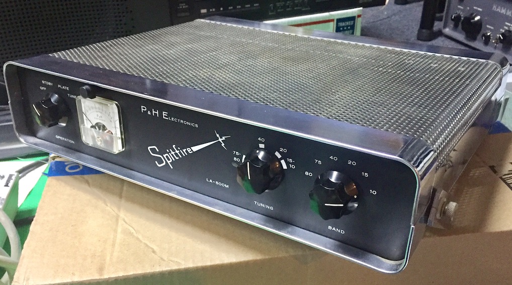
The early brochure from P&H, shows a slightly different looking front pannel. 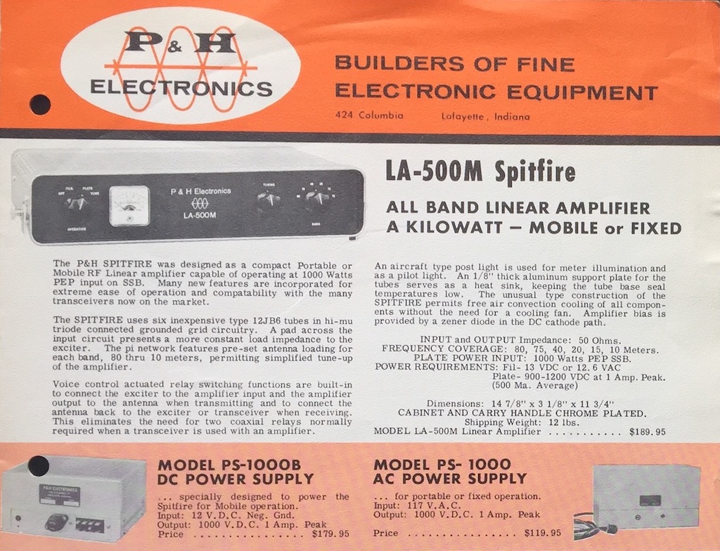
The QST ad from 1964 shows the front pannel design that matches what I have. 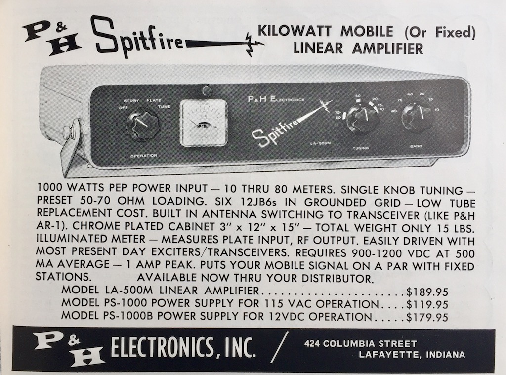
It is well designed and constructed. If you don't abuse the tube and use it as instructed in the manual, the tubes will last very long. It is to be driven for ICAS average output of 200-300W. With the PEP reading meter, the max output is between 450W - 600W, except for 10m. On 10m, the output drops to about 300W. 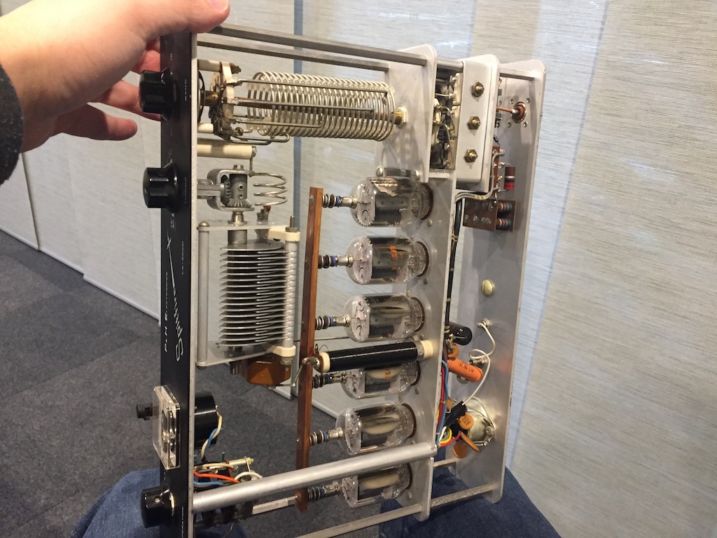
All six RCA 12JB6 were tested very good. All are date-coded to 69-17 (17th week of 1969), so the original tubes must have been replaced. The RCA 6JB6 or 12JB6 are known to not work well in Drake transceivers, especially on high bands, but they seem to be stable in the Spitfire. It is probably because the configuration is of grounded-grid type. 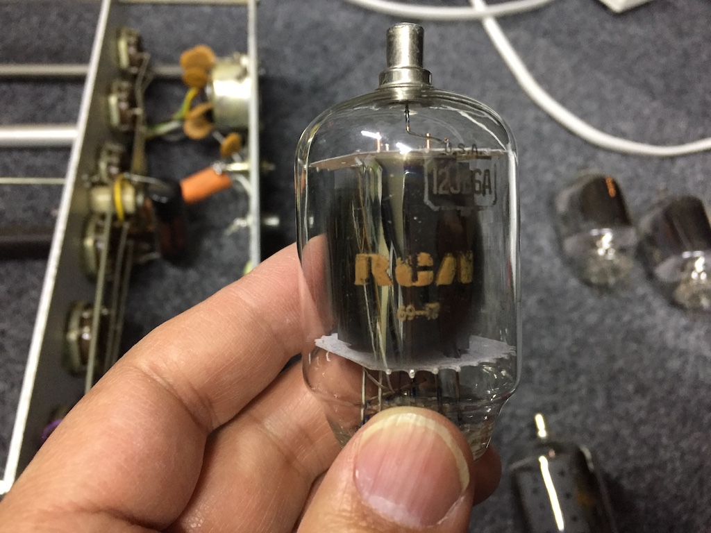
There were problems with the loading capacitors, which are set-and-forget kind of trim caps. The trimmers for 80m, 75m, 40m and 20m had not enough capacity. The one for 15m was fine. The 10m trimmer was shorting when tightened slightly. One of the mica plate must be broken. 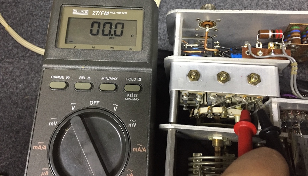
For 20m, I've added 180pF of padding. I had a 100pF 1kV ceramic and a 80pF 1kV surface mount cap. For 80m to 40m, a 560pF caps was used for padding. I had a perfect replacement for the broken 10m cap. 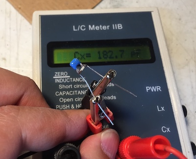
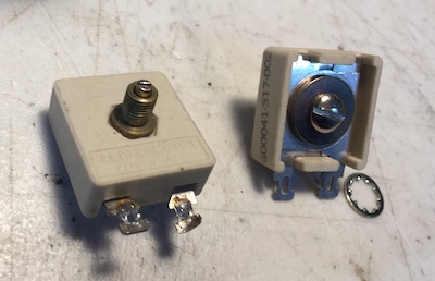
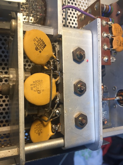
Installed padding caps. 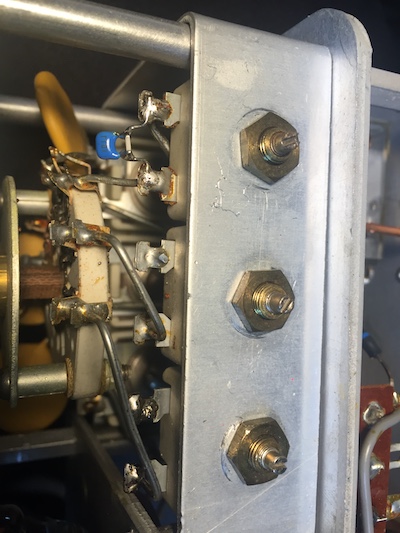
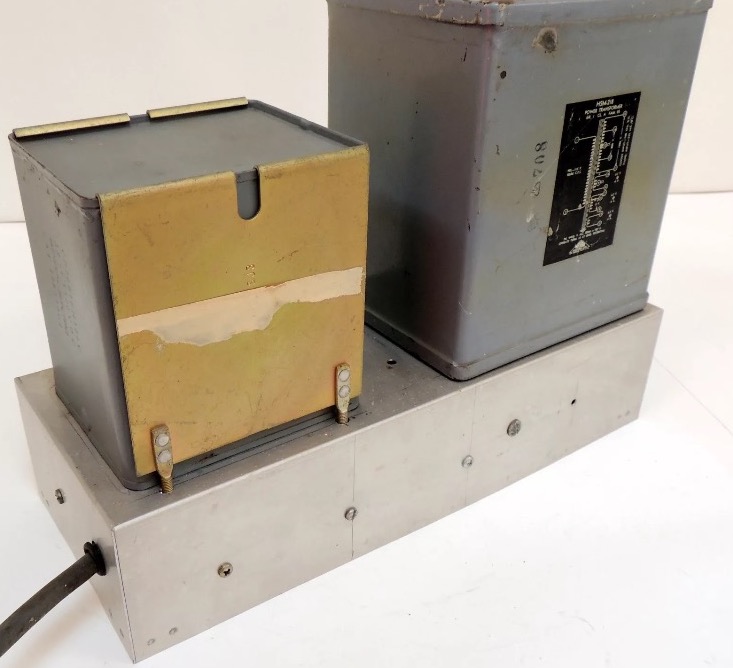
The power supply was a homebrew with a hefty Triad HSM-218 transformer and an oil-filled capacitor. 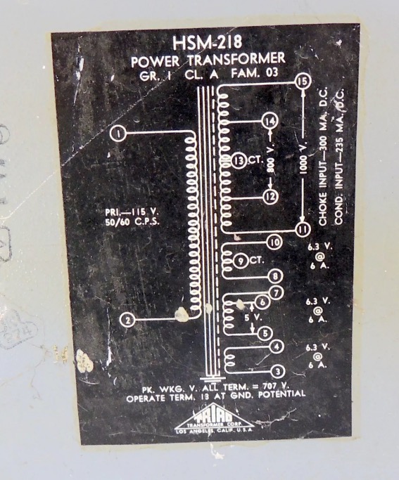
In Standby, the heater transformer is energized by the rotary single throw switch attached at the rea end of the mode selector. In Plate, the plate transformer powers on through the relay. The mode slector only powers the relay, so in-rush current does not go through the switch contacts. The plate current is measure across the 5 ohm resistor between the negative plate supply out and ground. In Tune, the metering circuit changes to measure relative output. 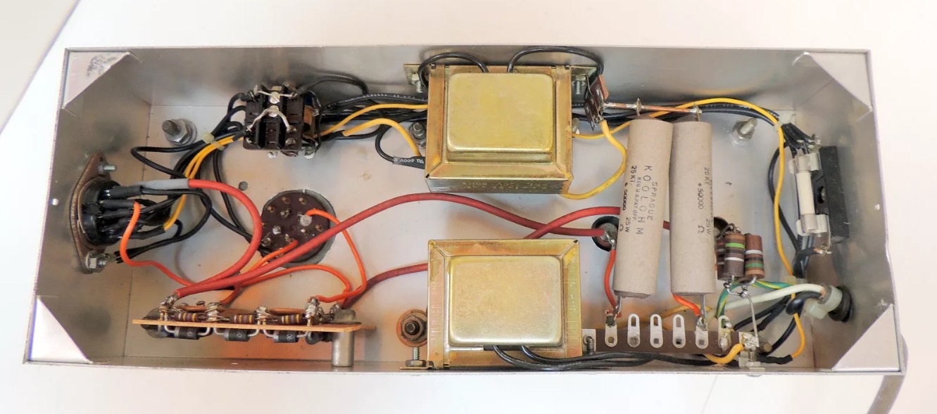
The HV was measured to be 1,177V at idle current of 50mA. It is very close to the estimated voltage of 800V x (123V/117V) * 1.414 = 1,189V. This drops to 964V at 831mA, which is 801W DC input. 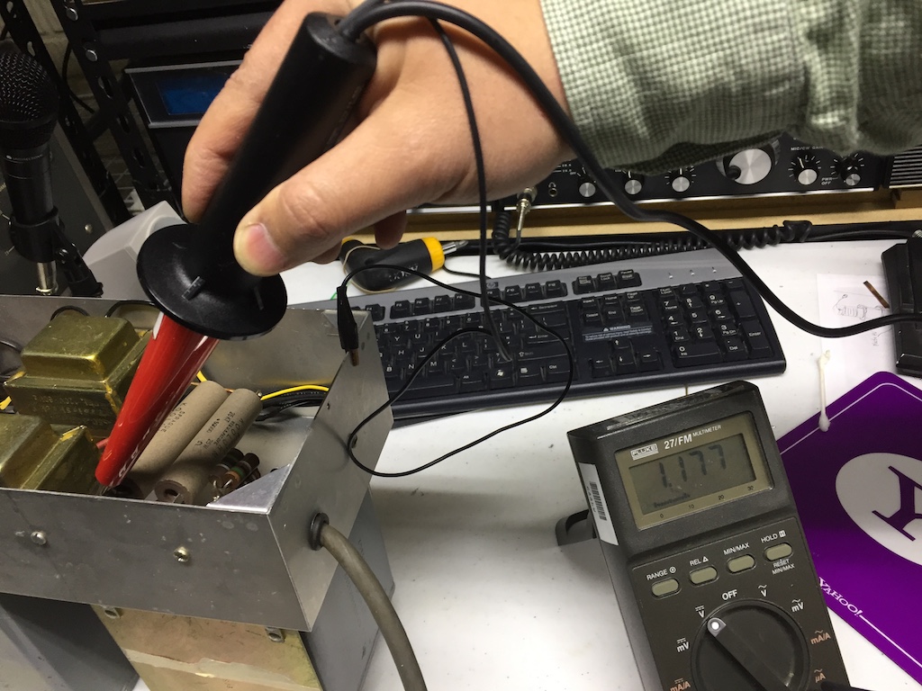
The top. 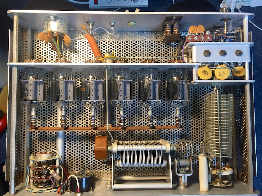
The bottom. 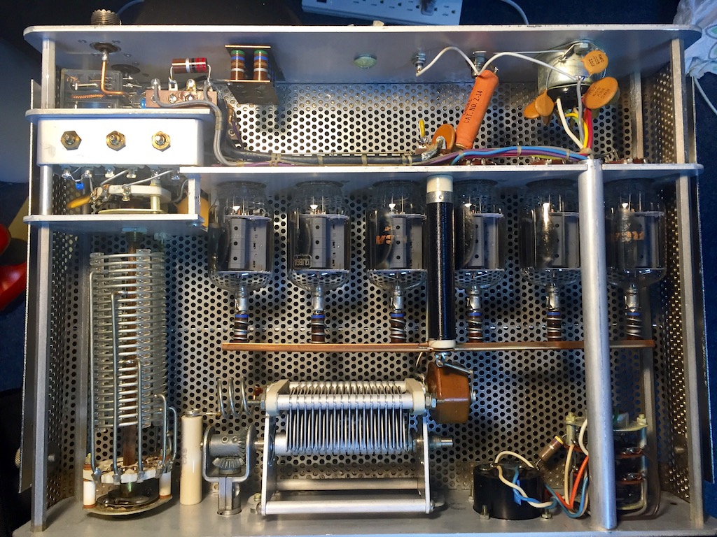
Copyright (C) 2017 Kihwal Lee |