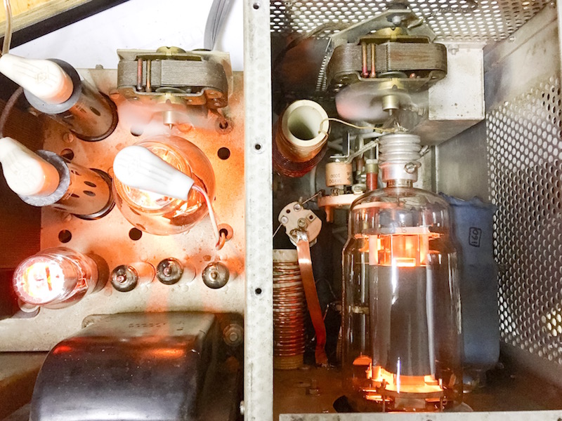
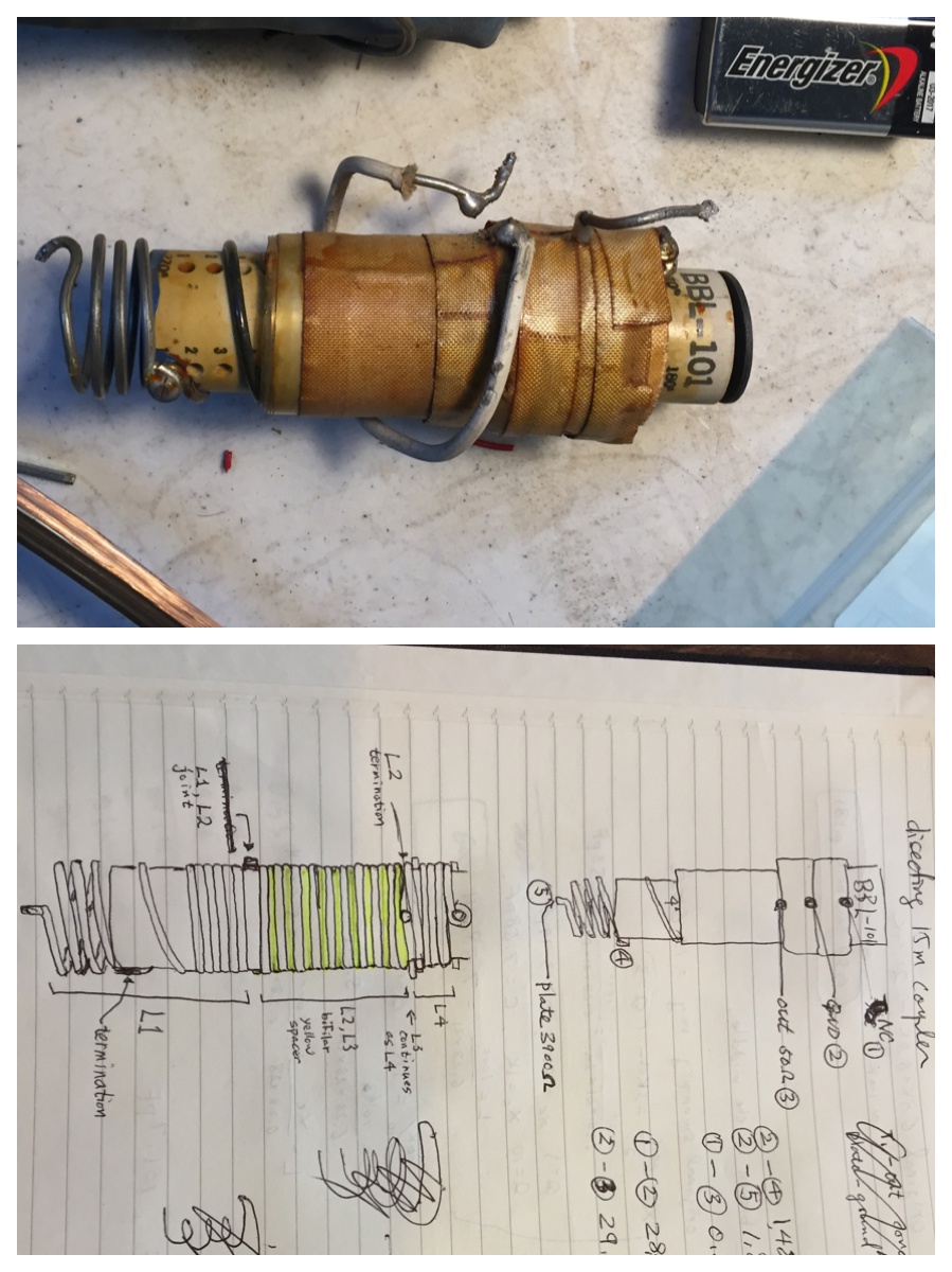
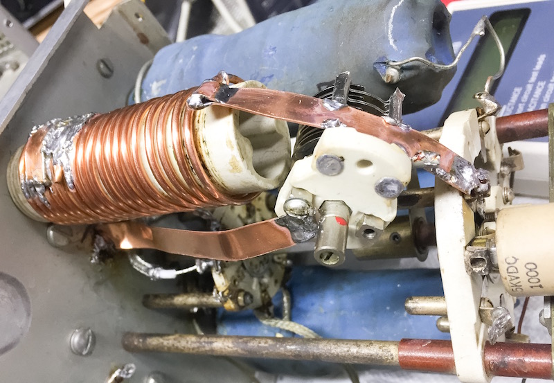
As a first step to repair the 15m, I bravely took apart the 15m coupler the other day. (See here) It felt like one of those mummy unwrapping party. After unwrapping layers of tapes and films, The top layer of L4 appeared. Underneath were windings, a part of L1, the bifilar L2/L3, and the rest of L4. They were all single layer and I found no shorts or broken wire. Some part of insulation on L1 was discolored, probably due to heat, but was still holding. It is possible that the heat slowly changed the dielectric characteristics of the spacing material, the insulation or the plastic film. It might be that the high band couplers are more sensitive to this kind of aging (capacitance change). Since I could not figure out what's actually wrong with the coupler, I decided to replace it with a pi matching network.
In order to achieve a wider matching bandwidth, the Q of the PI network has to be lower than the typical design. Various sources say the minimum should be 12 and preferably higher than 15. I thought the poor harmonic suppression won't be an issue because I can use an external LPF for 15m and 10m. Transforming 3900 ohm transforming to 50 ohm at Q=12 required approximately CP=82pF, L=3uH and CL=20pF. CP will be at the 50 ohm side, so its voltage rating doesn't have to be high. Let the peak output be 400W. Them, the peak voltage at the terminal is sqrt(50ohm*400W)=141V. I decided to use 630V ceramic caps there. For the plate side, I used 3kV parts.
Fixed loading capacitor is not too common, but the Heathkit HA-14 amp also did it. I planned to pad the plate capacitor as necessary with 12, 15, 18, 22pF ceramics. For variable part, I modified 50pF variable capacitor by removing every other rotor plates and collapsing two stators together. The resulting air gap was enough for 3kV DC.
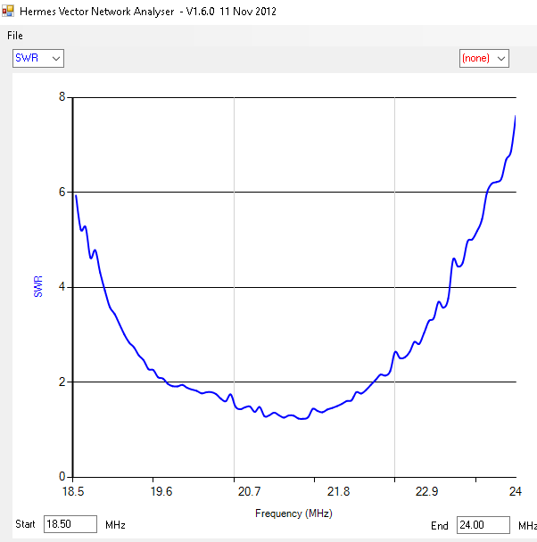
The experiment went fine. I first tried the network using a small airdux and low voltage capacitors, terminated with a 3900 ohm resistor. I was able to achieve a good matching network and the bandwidth was reasonable. I went ahead and wound the coil on a 1" ceramic coil form. After some adjustment, I obtained a coil with the inductance that is close to 3uH. With the actual components, the matching characteristics were again verified. But when I tested with the 813 tube plugged in, I could not obtain the matching point. Eventually I realized that the internal capacitance of the tube and stray capacitance were being added to the place capacitance. I pulled out the tube and placed a variable capacitor there. Using the working 20m coupler, I found the matching point by adjusting the cap. It was about 16pF and the 813 spec sheet says 16.5pF. Ah ha!. It is so basic, but somehow I managed to overlook it.
The total plate-side capacitance that is out of my control was about 30pF. The tube has 16.5pF, stray capacitance of about 10pF and a neutralizing type of capacitor set at about 5pF. I couldn't remove this cap since the working couplers must be dependent on it. 30pF is a lot of capacitance to work with on high bands! I couldn't lower the Q below a certain level. I shoot for 40pF so that I can hot the mark with the 30pF internal and the 20pF variable cap. Instead of completely remaking the network, I started by shorting out coil turns. As the inductance decreases, the required C would increase. I had a 200pF on the output (load) side. When I finally got a nice dip, The inductance was about 1.4uH.
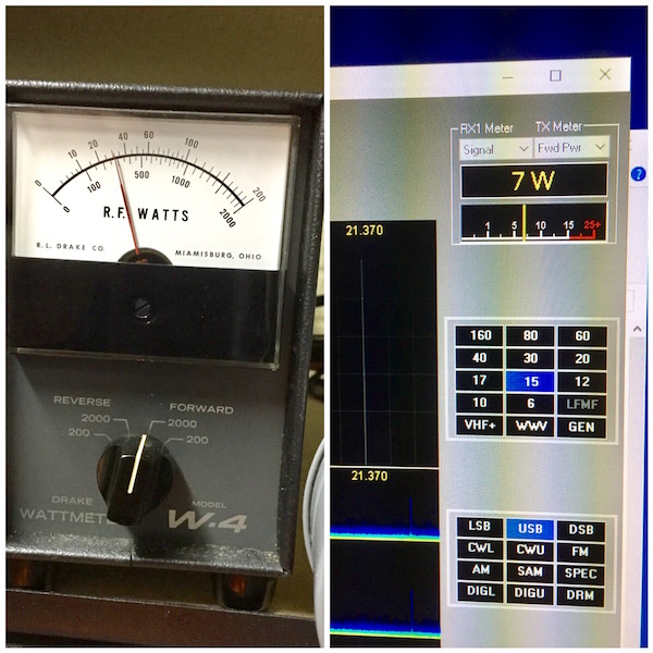
The cold adjustment point was spot on. That means the plate resistance is indeed 3900 ohms. I was finally getting real power output! With the faulty coupler, the maximum output was about 100W. With the pi-network, it was doing 300W with a 7W drive. Compared to other bands, this 15m configuration required more drive.
Now that I had an initial success with this approach, I went back to calculate the new PI network parameters. With the 1.4uH inductor, I could get Q=22.6, CP=43pF, CL=357pF. I padded the 200pF load capacitor to 330pF. A retest showed a much improved efficiency and a higher output.