I don't know whether these were enough to cause this, but the plate overload would trip everytime the place supply is turned on. Pressing down the reset for a second would made it work. It looked like the time-delay wasn't working and the in-rush current was tripping the overload protection (over 500mA). I replaced the 750 ohm resistor with a 2,000Ohm one. That created a delay of about 300-500ms and the overload wouldn't trip anymore. A 220uF was later added and the delay was about 1 second.
This was an easy and satisfying fix.
2) High SWR protection relay.
The high SWR protection circuit applies cut-off bias (-320V) when SWR is over the threshold. In the 600L, the relay coil was broken somewhere. This is a common problem in this type of relays. I replaced it with a modern 110V-10kohm coil relay, but did not work properly. It works the first time, but if plate supply is cut and re-engaged, it wasn't getting energized enough to fully engage the contacts. I didn't follow it up further, since the relay had a lever to manually "turn on". This 600L is not a clean/intact one, so I do not want to spend $60 on the relay coil. I will revisit and make it work eventually.
3) Output broadband coupler characteristics.
Now this is the real challenge. I've read through the patent by Joe Batchelor and found it was written during the development of the 600L. It mentions a 813 amp as an example and talks about a 3900 ohm plate load resistance. I've looked many other 813 amp projects and this seemed a bit low, but later experiment verified that 3900 ohm is indeed the design parameter used in the 600L output couplers.
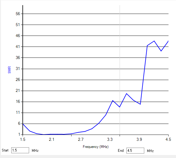
Because of malfunction in 15m and 10m, I started measuring the characteristics of the output couplers. I connected a 10k pot between the plate of 813 and ground. While feeding a small signal to the amp output, the pot was adjested to show the lowest SWR. The ANAN-10 SDR was used as signal source as well as measuring SWR. From 160m through 20m, the optimal pot settings ranged from 3800 ohm to 4100 ohm. So the plate resistance mentioned in the patent doc matches that of 600L design. Then I measured their characteristics at 3900 ohm. The 15m and 10m couplers showed unusual characteristics, confirming my suspicion of them being defective.
[160m coupler]
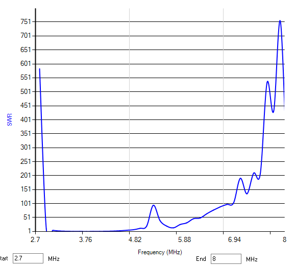
[80m coupler]
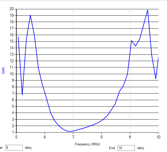
[40m coupler]
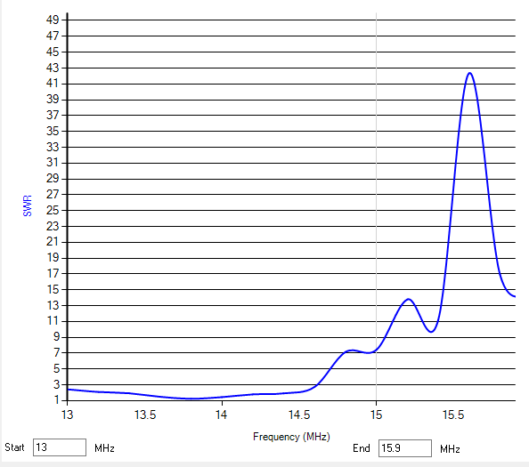
[20m coupler]
[15m coupler with 3900 ohm]
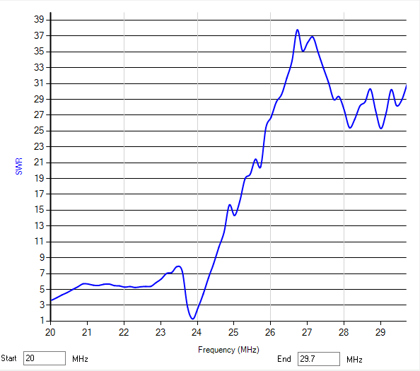
[15m coupler with 1000 ohm]
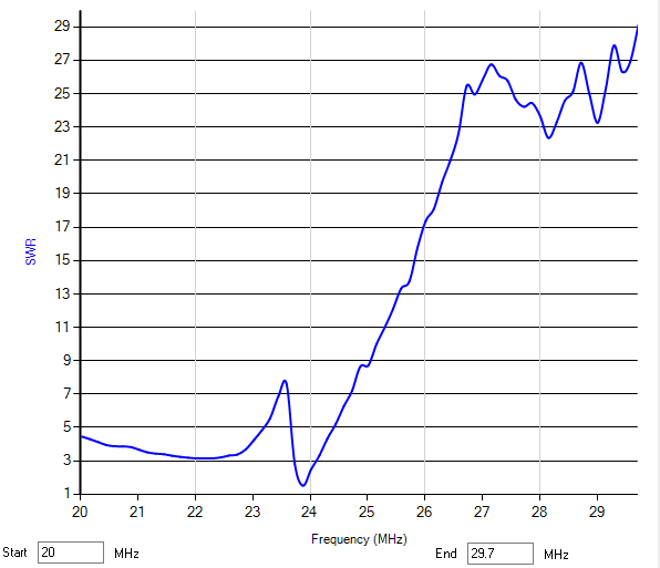
[10m coupler with 3900 ohm]
[10m coupler with 850 ohm - the dip is likely due to the resonance with the extra capacitor]
[The 10m coupler has an extra tab and is connected to a neutralizing type air gap capacitor]
The 10m coupler has a rather sharp dip, which moves as the extra capacitor is tuned. Some version of the 600L does not have this cap.
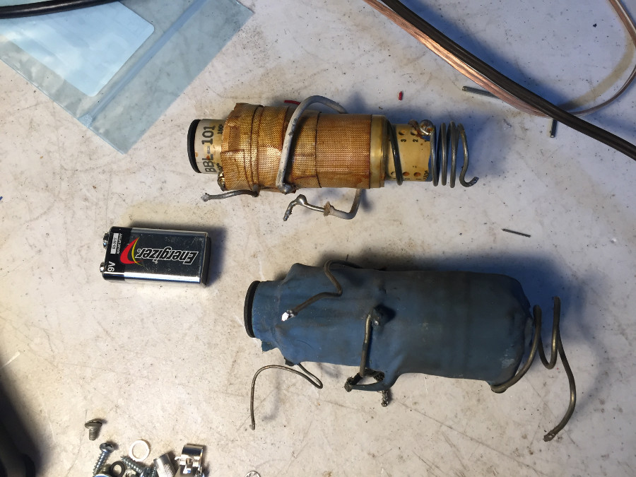
[The 15m and 10m output couplers]
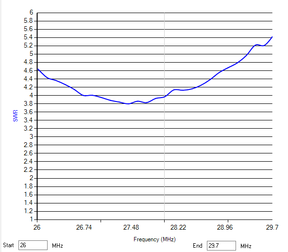
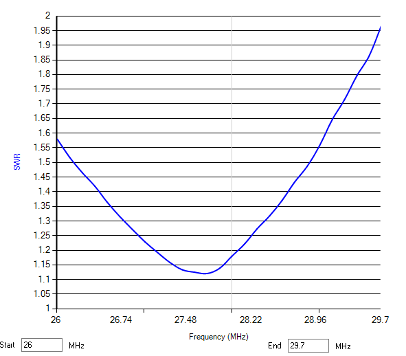
I might be able to get the replacement couplers from Nick Tusa, but they will be expensive. I could try a pi network with a lower Q. I experimented with one design for 15m with Q=12. Roughly 20pF - 3uH - 82pF. It was matching 3900 ohm to 50 ohm close enough between 21.050 and 21.450, so it is a possibility. I will install a LPF, so harmonic supression is not as important.
4) Input couplers
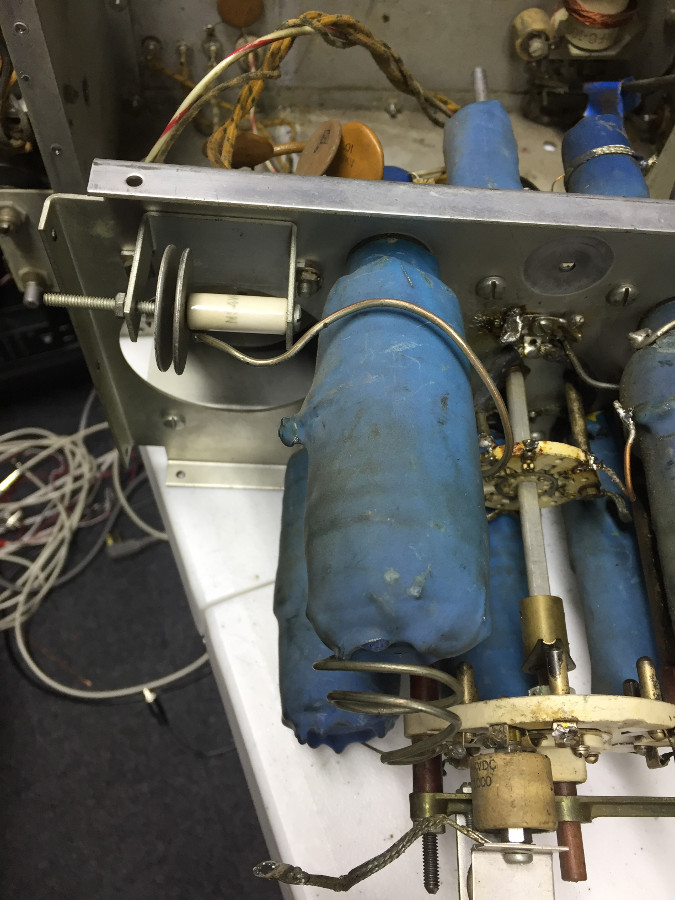
I took a deep breath and started taking apart the RF section. After unmounting the band switch and unscrewing four screws, the whole assembly came out easily. I could clealy see the 15m output couple was replaced as well as 80m and 40m input couplers. The malfunctioning 10m input coupler had no continuity (L1-L3 side) unlike others. I later found out that it is a simple case of broken ground wire. When someone messed with the input circuit by adding resisters here and there, he accidentally unsoldered the ground wire from ther 10m input coupler. I think he did this "repair" because the grid swamping resistor was cooked. It was measured to be 21.54k instead of the original 13.6k. For 10m, he had added 33k in parallel, which brought down to about 13k, close to the original value. Well, he should have actually replaced the cooked swamping resistor. I removed all band-aid resistors and replaced the swamping resistors. Also the replacement couplers for 80m and 40m were not really well mounted and connected. I re-did them. The replacements seemed to have come from Central Electronics. The construction is of the same style of 100V/200V's.
At this point, I can't reliably test the input circuit until the output couplers are fixed.
[CE 600L, RF section taken out]
